Description
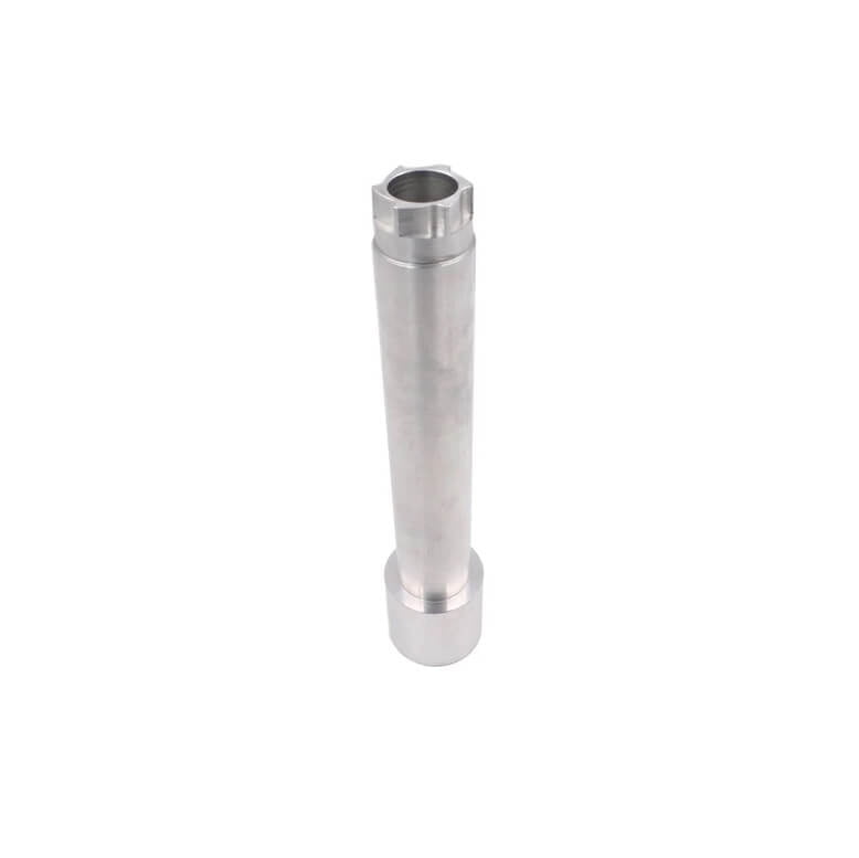
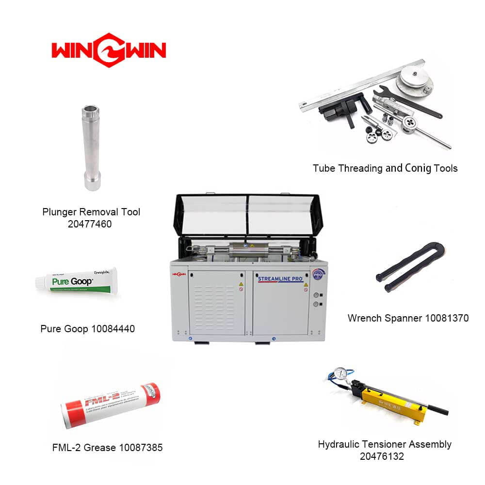
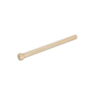
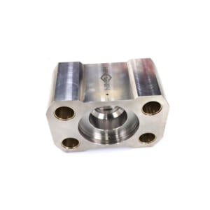
90K Water Jet Tool: Plunger Removal Tool 20477460
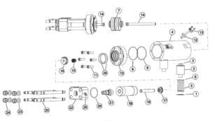
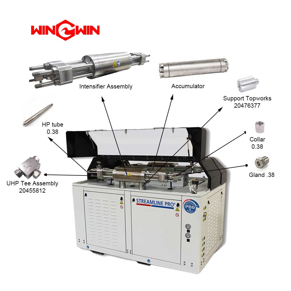
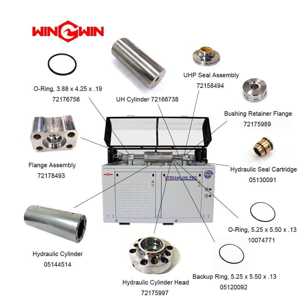
Article | Numéro de pièce | Description | Quantité | Article | Numéro de pièce | Description | Quantité |
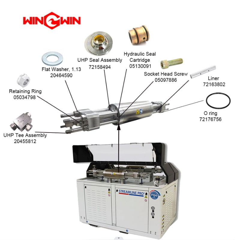
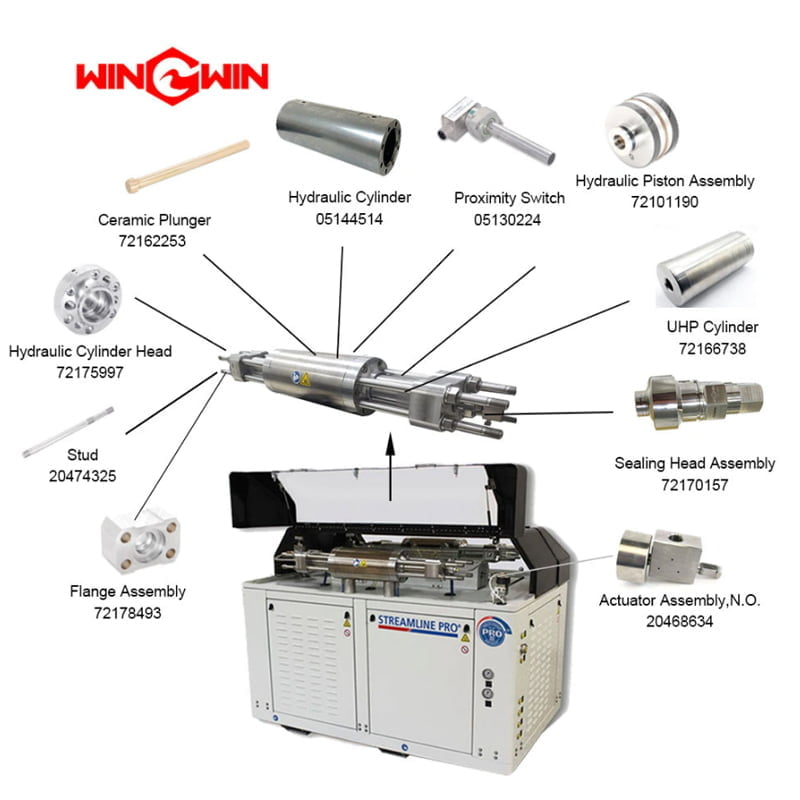
1 | 05146592 | Joint d’étanchéité, Topworks Support | 2 | 14 | 72162253 | Ventouse | 2 |
2 | 20476377 | Soutien, Topworks | 2 | 15 | 05130091 | Cartouche de joint hydraulique | 2 |
3 | 10118206 | Joint torique, 1.31×1.56× .13 | 2 | 16 | 72175989 | Bride de retenue de bague | 2 |
4 | 05144514 | Vérin hydraulique | 1 | 17 | 72158494 | Assemblage de joints UHP | 2 |
5 | 05098991 | Vis à tête creuse, 3/8-16×3-3/4 | 8 | 18 | 72166738 | Cylindre UHP | 2 |
6 | 95688743 | Rondelle de blocage, .38 | 8 | 19 | 72163802 | Paquebot | 2 |
7 | 72101190 | Assemblage du piston | 1 | 20 | 20474325 | Goujon, 1-1/8-12×18.31 | 8 |
8 | 10074771 | Joint torique, 5.25×5.50× .13 | 2 | 21 | 72170157 | Assemblage de la tête de scellage | 2 |
9 | 05120092 | Anneau de secours, 5.25×5.50× .13 | 2 | 22 | 72178493 | Assemblage de brides | 2 |
10 | 72175997 | Culasse hydraulique | 2 | 23 | 20464590 | Rondelle plate, 1.13 | 8 |
11 | 05097886 | Vis à tête creuse, 3/4-16×2-1/4 | 12 | 24 | 20461761 | Écrou hexagonal, 1-1/8-12 | 8 |
12 | 05144183 | Ensemble d’entretoise, interrupteur de proximité | 2 | 25 | 20489339 | Adaptateur, JIC/Tuyau, 50× .38 | 1 |
05144191 | Joint torique, .69× .88× .09 | 26 | 72176756 | Joint torique, 3,88×4,25× .19 | 6 | ||
13 | 72141569 | Kit, Détecteur de proximité | 2 | ||||
| 72134224 | Commutateur de proximité | ||||||
95119012 | Vis à tête creuse, 1/4-20×1 |
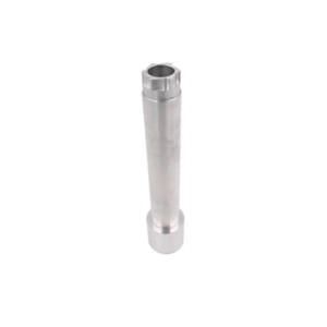
The Plunger Removal Tool with part number 20477460 is a specialized water jet tool used for removing the plunger assembly from 90k waterjet pumps.
The plunger assembly is a critical component of the pump, responsible for creating the high-pressure water stream that is used for cutting or cleaning.
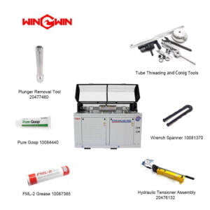
The Plunger Removal Tool is designed to make it easier and more efficient to remove the plunger assembly from the pump for maintenance or repair.
– Design: The Plunger Removal Tool typically consists of a mounting plate, support bracket, hydraulic cylinder, and other components as needed.
The mounting plate and support bracket are designed to securely attach the water jet tool to the pump, while the hydraulic cylinder is used to apply force to the plunger assembly to remove it from the pump.
– Material: The components of the Plunger Removal Tool are typically made from high-strength materials such as steel or aluminum, which can withstand the forces involved in the pump system.
The water jet tool must also be resistant to wear and corrosion from the water and abrasive particles.
– Maintenance: Proper maintenance and inspection of the Plunger Removal Tool is important to ensure its continued reliability and performance.
Over time, the components of the water jet tool may become worn or damaged, which could compromise its ability to remove the plunger assembly from the pump.
Regular inspection and replacement of worn or damaged components can help prevent these problems and ensure the safe and efficient operation of the pump.
– Compatibility: It’s important to ensure that the Plunger Removal Tool is compatible with the specific model of waterjet pump being used.
The water jet tool must be designed to work with the mounting points and other components of the pump.
And it must be able to apply the necessary force to remove the plunger assembly.
Using an incompatible water jet tool could lead to damage to the pump or the tool itself.
To use the Plunger Removal Tool, the pump must first be disassembled to access the plunger assembly.
The tool is then mounted onto the pump and the hydraulic cylinder is used to apply force to the plunger assembly, pushing it out of its position in the pump.
Once the plunger assembly is removed, it can be inspected, repaired, or replaced as needed.
What is the using method of Plunger Removal Tool?
1. Shut off the water and power supply
Before beginning any maintenance or service work on the waterjet pump, it is important to shut off the water and power supply to ensure safety.
2. Remove the high-pressure hose
Disconnect the high-pressure hose from the waterjet pump to access the plunger.
3. Remove the plunger
Insert the plunger removal tool into the plunger and turn the tool counterclockwise to loosen and remove the plunger from the pump. The plunger removal tool is designed to fit the size and shape of the plunger, so be sure to use the correct tool for the specific plunger being removed.
4. Inspect the plunger
Once the plunger is removed, check to see if it should be replaced.
5. Clean the plunger bore
Clean the plunger bore in the pump body thoroughly to remove any dirt, debris, or other contaminants.
6. Install the new plunger
Insert the new plunger into the plunger bore and tighten it using the plunger removal tool. Must follow our recommended torque settings.
7. Reconnect the high-pressure hose
Reconnect the high-pressure hose to the waterjet pump.
8. Test the waterjet pump
Once the plunger has been replaced and the high-pressure hose has been reconnected, test the waterjet pump to ensure that it is operating properly.
Turn on the water and power supply, and run the pump for a short period of time to check for leaks or other issues.
It is important to follow our manufacturer’s recommended procedures for using the plunger removal tool and maintaining the 90000psi waterjet pump.
Here are some other tips:
a. Use the correct plunger removal tool
The plunger removal tool is designed to fit the size and shape of the plunger, so it is important to use the correct tool for the specific plunger being removed.
b. Use proper technique
When using the plunger removal tool, use proper technique to prevent injury and damage to the pump or other components.
c. Store the plunger removal tool properly
Store the plunger removal tool in a clean and dry environment, such as a toolbox or a cabinet.
Avoid exposing the tool to moisture, heat, or corrosive substances, asthis can cause damage or rust.
Any other requirements for the water jet tool, please Consultez-nous.

